Hydraulic powered pillar punch press

Hydraulic powered pillar punch press

Hydraulic powered pillar punch press

REQUEST A QUOTE


Pillar Punch Presses are attractive for their ability to adapt easily for using different type, size or capacity power units that can be mounted on the top surface of the two upper railings. These models are best to be used with hydraulic power.

• Pillar Punch Presses are an excellent choice for budget oriented applications, yet high output or tonnage is required.

• Your existing blanking and or forming tools can be installed with ease, or custom designed tools may be supplied with the press.

• Operator control, mounting of the press, and safety devices are similar to the other presses and should be specified before ordering pillar punch presses from Vortool Manufacturing Ltd..

• The physical size and capacity of any of the presses may be specified, or can be chosen for you based on the project that you wish to use the press for.


Vortool Manufacturing

Vortool Manufacturing Ltd.

Unit 240 19358-96 Ave.

Surrey, BC V4N 4C1 Canada


Call: 604-239-7218 | Email


Made in Canada


Air to oil powered C frame modular bench top punch press


Air to Oil Powered C Frame Modular Punch Press

The Air to Oil Powered C Frame Modular Punch Press product line bVortool Manufacturing Ltd. is commonly used for various purposes. The space saving and vertical style design make this unit attractive for different reasons.


•  The double sided C frame provides exceptional strength while maintaining the small foot print of about 5 inches wide only.


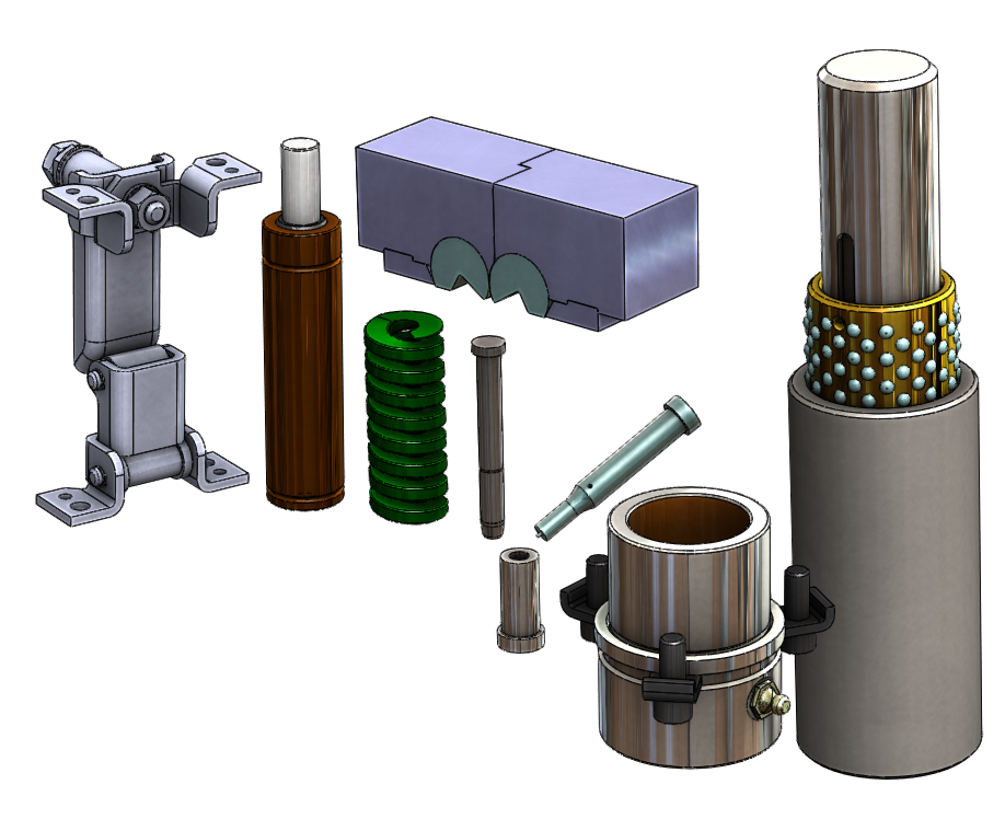
• The power source can be air, hydraulic or the combination of the two. The sample is equipped with an air to oil cylinder, using regular compressed shop air to operate. There are many models to choose from to suit most applications. The cylinders range between 1.5 to 12.5 Ton capacity. Other models are also available that are capable producing up to 60 tons at 120 psi air pressure.


• Conventional hydraulic cylinders can be also used for higher tonnage requirement. To keep the foot print to the minimum, high pressure hydraulic pumps and cylinders can be installed, capable for 80 tons output using a small, 5" bore cylinder at 10,000 psi.


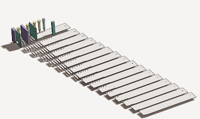
• Tools or metal stamping tooling components to be mounted on the horizontal platform. This c frame press can be easily bolted on an existing bench top or shipped with a dedicated stand. These stands could be floor mounted or have lockable casters for even greater mobility.


• There are different operator controls to choose from. You can have a foot pedal or palm buttons with or without an anti tie down module. The control may be built pedestal style and can be equipped with non contact finger sensors to activate each cycle. Depending on the application requirement, a more sophisticated PLC integrated system is available.


• The above options are also available with the other press models such as the Box Frame Press, the Three Platen Press, or the Pillar Press.


Vortool Manufacturing

Vortool Manufacturing Ltd.

Unit 240 19358-96 Ave.

Surrey, BC V4N 4C1 Canada


Call: 604-239-7218 | Email


Made in Canada


Strip layout design concept for metal stamping dies

Strip layout design concept for metal stamping dies

Strip layout design concept for metal stamping

All metal stamping designs should start with the basics. A solid foundation is required with both a visual and technical guide to progress further. The strip layout is the starting point of a metal stamping design which is the foundation or plan to manufacture and build the actual tool.

The strip layout design has several purposes. Once complete, it gives a visual representation to the manufacturing facility and to the client to have a good idea how the tool will work and how each progression or step will be made once the strip or coil is inserted into the die. The stamping can then begin.

This visual guide is the most important aid for the metal stamping die designer. It reveals details to clearly see how each feature must be made at each progression as the strip advances into the tool. Then important decisions can be made to simplify the final design or make it fit for automation and most importantly to improve it before it even starts.

The strip layout should include punches, form blocks, pilots, and some die blocks in order to make it clear how the tool will work and produce the parts. It is to ensure that the tool will do exactly what it is supposed to do.

Tool and die designers who neglect putting enough effort into this process, often end up with design errors. As a result, the manufactured stamping tools don’t perform well enough or don’t work at all. In that case costly modifications are necessary to correct mistakes before production can start. Usually these tools are notorious for break downs and require maintenance more often than others.


Strip layout design concept for metal stamping dies


The proper tool and die design of a strip layout gives a piece of mind to the tool and die designer to proceed in the right direction. It is insurance for the end user or those who finance the project and want to be sure that their investments are in good hands with the tool working efficiently for a long period of time without breaking down. This is what it is all about. The sole purpose of a metal stamping tool is to produce as many identical high quality parts as possible at the shortest amount of time without stopping. Every time the tool requires maintenance and is not producing, it takes money away and becomes less efficient.

A good metal stamping die starts with a solid foundation, a good strip layout that gives the chance to eliminate future nuances, and to build world class tools that you can count on.

Vortool Manufacturing

Vortool Manufacturing Ltd.

Unit 240 19358-96 Ave.

Surrey, BC V4N 4C1 Canada


Call: 604-239-7218 | Email


Made in Canada


Design considerations for stamping tools and dies

Design considerations for metal stamping tools and dies

Design considerations for metal stamping tools and dies

Metal stamping die design considerations or decisions are driven by a number of factors in tool and die design.


However there are a few mayor points that should not be missed and must be included in the decision making process. You could design and build an inexpensive fabricated tool or you could make one that is a top of the line master piece.


How do You Decide Which One to Make?

Your customer will tell you what they need, what material the stamped parts are, how many parts should be stamped, when they want the finished parts, and how much they are willing to pay and so on.
These are important guide lines toward the metal stamping die design. They tell you what you can do and what you can’t. They set some boundaries.


The part itself is one of the major contributors that guide you through what the minimum requirements are toward the tool. It will help you with what you need in order to produce the particular part.
You may raise questions that need to be answered. How efficiently will the parts be produced? How long will the tool last? How user friendly should the tool be? What are the variables that can be implement in the design?


The Above General Guide Lines Should be Specified More in Detail

  • How many parts will be produced per run, monthly or in the lifetime of the tool? If the amount of production is low, you will know that the tool will likely be manually operated and be budget oriented. If e.g. 5,000 parts are to be made every week for the next two years, than you know it is a high demand tool and automation and continuous operation is required. The tool must be designed accordingly. More time and money can be spent to make the suitable tooling.
  • Low production rate equals inexpensive tooling components, unsophisticated guides, supports, etc.
  • On the other hand if the metal stamping tool is running all the time, then you will need to build a tool that lasts. It will require less frequent tool and die maintenance, and be built for high speed automation. The tool steel should be higher quality, and more suitable for extended use. In this case instead of using e.g. A2 or D2 material, consider using M2 with coated surfaces or Vanadis 4 Extra or comparable. For the extra cost, these tool steel will last many times longer before sharpening is required. Use a ball bearing guide system, instead of standard bronze plated bushings and standard die pins. The ball guided system is better for high speed punch presses and high speed stamping.
  • Pressure plates require springs behind them to generate enough force. Consider using gas springs. They are generally suitable for high speed stamping, and about 250 spm and rated about 1 million strokes before servicing. They are also more powerful than conventional die springs with the same footprint. You can use punches with ejector pins in them to push off slugs that are serious obstacles in automated stampings. You can also use die buttons with slug control that keep the slugs in the die button, preventing slug pulling. Slugs pulled back onto the die surface area can jam the strip and cause the feeder to buckle the coil. If this happens, your tooling may be at risk for serious damage.
  • Bending is generally done using a wipe form method. The parts eventually gull and have heavy marks. The form sections constantly require polishing, causing downtime and quality issues. Ready benders can eliminate most of these problems, where the bends have simple straight features. This method completely eliminates parts sticking into the form die, as they require less pressure and will not mark the part as much or just simply eliminate it altogether. It is a perfect solution for pre-painted strips to stamp.
  • Stock pushers are designed for automated stamping and have a superior feature that make their use a preferred choice.
  • At upstroke of the press, they release the force applied to the edge of the strip or coil entirely, allowing a resistance free strip advancement. The applied pressure is adjustable, and you can design the engagement timing as you need it. The pilot punches can locate the strip perfectly before you lock its position for the duration of the cut.
  • Another contributor to your metal stamping tooling design is to know what press or presses will be used for stamping. Your tool must be compatible and fit the desired press or presses. You may want to consider making 3D models of the presses with the vital features that are necessary for your tool design.
  • The general requirement toward any stamping tool and for their design is that it should cost as little as possible, yet produce the most amount of parts at the best quality, should not break down, and will last longer than the anticipated life span of the tool. This perfect scenario should be achieved at all times. Compromises sometimes must be made and accepted, but not be part of your design.
  • The guide lines or restrictions that are set by your client, your tool and die manufacturing facility or your ability, will have an impact of the outcome of your design and ultimately of the stamping tools and the produced parts.


Metal stamping die design


Vortool Manufacturing

Vortool Manufacturing Ltd.

Unit 240 19358-96 Ave.

Surrey, BC V4N 4C1 Canada


Call: 604-239-7218 | Email


Made in Canada