Optimum cutting clearance for blanking sheet metal
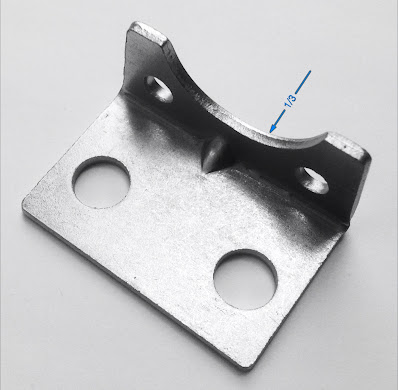
At optimum cutting clearance for blanking sheet metal at any given thickness, the sheared edge or the shiny band should be about 1/3 of the material thickness. The ripped or break away surface is 2/3.
When the band is too small, it indicates that the cutting clearance is too much. The bur is generally larger than normal, and the part may not be as flat as should be.
When the band is too large, it indicates that the clearance is too small. The bur is large and uneven, so the punch may stick in the strip and stripping is difficult. Die and or punch edges chip often. It is because the strip is extremely tight on the punch, and as it pulls out, the edge (weakest point) may rip off, especially when the ground surface is not as smooth as should be.
Generally I use 10% clearance per side between 1- 2.5 mm and 12-15% for thicker material. The thinner the material, the clearance gets smaller as well. Over time I collected data from cutting clearances and results, and I use this data as average in my calculations. There is a variable of soft, medium or hard material to be blanked. I developed an iPhone app to simply type in the material thickness and hardness of the stock that gives me the calculated clearance per side and diameter.
There is a misconception among toolmakers that absolute centered alignment of the punch and die is less critical when the sheet (stock or coupon) is thicker. This is wrong. When the components are misaligned, the bur is generally larger on one side and the other not. What happens is that the pressure required to blank, e.g. 40 tons, will force the punch out of its position and try to get back to the center. This deflection creates more problems than most people would think.
• As a result of the above, the parallel movement of the die set is compromised and slightly tilted. This would compound the initial problem.
• The punch press will also suffer. The blanking pressure is shifting sideways and will wear off the press components sooner. The improper clearance also affects the tonnage required and is greater than usual. Used punch presses are generally worn and always have a little slack. It means that even a 200 ton press’ RAM could be pushed back for a moment before it can go down with full power. This slight hesitation also creates movement while cutting, and it is, again affecting the life of the punch and die edges. If this happens, the cut edge will look different. Sometimes the bottom edge can measure about the same as the upper part and the edge may have horizontal lines, small bands.
When I design metal stamping dies, it is important for me that the tool stays in production as long as possible. It makes money. When the tool is off the press, it does not only require labour, time and money but will not produce anything either, and this is an even bigger loss. So, I always ensure that the clearances are correct and the alignment is absolutely centered, regardless of the thickness of the material. I use a similar precision for alignment between punches and dies, regardless if the thickness is 0.025 mm or 13 mm.
When the band is too large, it indicates that the clearance is too small. The bur is large and uneven, so the punch may stick in the strip and stripping is difficult. Die and or punch edges chip often. It is because the strip is extremely tight on the punch, and as it pulls out, the edge (weakest point) may rip off, especially when the ground surface is not as smooth as should be.
Generally I use 10% clearance per side between 1- 2.5 mm and 12-15% for thicker material. The thinner the material, the clearance gets smaller as well. Over time I collected data from cutting clearances and results, and I use this data as average in my calculations. There is a variable of soft, medium or hard material to be blanked. I developed an iPhone app to simply type in the material thickness and hardness of the stock that gives me the calculated clearance per side and diameter.
There is a misconception among toolmakers that absolute centered alignment of the punch and die is less critical when the sheet (stock or coupon) is thicker. This is wrong. When the components are misaligned, the bur is generally larger on one side and the other not. What happens is that the pressure required to blank, e.g. 40 tons, will force the punch out of its position and try to get back to the center. This deflection creates more problems than most people would think.
• Excess bur on one side.
• Flex, or movement while cutting. This movement will cut the life span (between sharpening by ~70%. Any side movement is the cause for most tooling problems.
• Excess strain on die components, guide pins and bushings.
• As a result of the above, the parallel movement of the die set is compromised and slightly tilted. This would compound the initial problem.
• The punch press will also suffer. The blanking pressure is shifting sideways and will wear off the press components sooner. The improper clearance also affects the tonnage required and is greater than usual. Used punch presses are generally worn and always have a little slack. It means that even a 200 ton press’ RAM could be pushed back for a moment before it can go down with full power. This slight hesitation also creates movement while cutting, and it is, again affecting the life of the punch and die edges. If this happens, the cut edge will look different. Sometimes the bottom edge can measure about the same as the upper part and the edge may have horizontal lines, small bands.
When I design metal stamping dies, it is important for me that the tool stays in production as long as possible. It makes money. When the tool is off the press, it does not only require labour, time and money but will not produce anything either, and this is an even bigger loss. So, I always ensure that the clearances are correct and the alignment is absolutely centered, regardless of the thickness of the material. I use a similar precision for alignment between punches and dies, regardless if the thickness is 0.025 mm or 13 mm.
Progressive blanking tool design
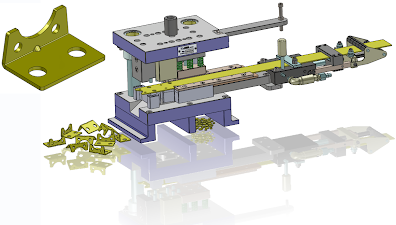
Precision progressive blanking tool design
The progressive metal stamping tool and die design consists of all the necessary features that any stamping tool should have from ease of use to high accuracy to reliable operation for a long time. It includes strip feed and guide, stripping, slug separation, and feeder actuation. As an option the tool can be used as a manually operated tool without the air feeder using strips instead of coil.
The cutting components are designed to be made of hardened tool steel that ensures long usability. Choosing the right alloy for the application and the proper design for the tool can greatly affect the life of the tool. As a result it can operate trouble free for longer, saving on maintenance, and reduce or eliminate downtime and minimize costs that are associated with the value of the final product.
This progressive blanking tool was designed using SolidWorks 3D CAD. Shop drawings, and files generated from the models seamlessly fit into any machine shop or tool room's profile.
High precision metal blanking tool design
High precision blanking tool design and manufacturing
Special products require special tooling and design. Blanking thin foil type material is a challenge of its own. E.g., a 0.002 - 0.005 thickness stock to be blanked requires such small amount of cutting clearance that it is a very difficult task for most tool makers and for the equipment to do properly.
For this particular design the finished blank was made of three layers. There were two carbon film layers of 0.003 thick with a copper foil between 0.0005 thickness. The requirements were the following:
- The part must be perfect, have no bur at all.
- Part is rejected if the carbon chips off from the metal.
- Part is rejected if the carbon is separated from the metal at any given area.
The customer provided samples, made by others that did not meet the request and were then rejected.
- The above criteria was achieved by using the right amount of cutting clearance for the design that this particular material needed.
- To avoid separation of the layers, the blank must have the least amount of flexing.
- To eliminate chipping of the brittle carbon layers that were only semi bonded to the copper were another challenge.
- A gentle even holding pressure was required to hold the material while it was blanked, while reducing the travel distance of the blank inside the die cavity.
- To accommodate all of the above, the tool had to be well guided, with low impact movement with no vibration or sudden shocks.
The result was excellent as expected, and the parts came out perfect.
The combination of a good metal stamping die design and precision tool and die manufacturing was the key to this success.
Subscribe to:
Posts (Atom)
